Saturday, 6 April 2019

Bike Servicing (Tips and Tricks You should Know)

Maybe you have bought your brand new motorcycle and the excitement is still in the air. Everyone loves the experience of riding the motorcycle and the sensation of wind passing by their faces. However, there is a step beyond that you could go by repairing your own motorcycle with quality hand tools in automotive. Basic knowledge about motorcycle servicing is required for every rider. Imagining a ride through woods and sudden mechanical
failure in bike can create great tension as you can’t expect a bike mechanic to be available at
remote places. But it can be avoided if owner have basic knowledge about servicing and maintenance. Many two-wheeler owners are unaware of the particulars of bike servicing and maintenance and wonder if the service mechanic is right or wrong in suggesting replacing some spare parts after certain interval.
It is not necessary to have full mechanical knowledge about how to perform simple home servicing tasks; some decent tools and a little common sense are all you need to keep your bike in healthy condition.
At first, owner should get hold of a workshop manual for his/her bike for a better understanding of how each task should be carried out. Most company will give pictures detailing each part of the processes; and also a good manual also list the necessary tools owner will need to complete the job.
Now, here is the list of tool set that will be most handy to you in case of a bike repair:
·        Socket wrench set,
·        Wrenches,
·        Screwdrivers,
·        Spanner,
·        Hex bit sockets,
·        Impact wrench/ driver,
·        Hammer,
·        Pressure gage,
·        Nitrile gloves,
·        Rags,
·        Funnel,
·        Needle nose pliers,
·        Spare fuses,
·        Penetrating oil,
·        Chain lube,
Full motorcycle service check list:
It is legal duty of every motorcycle owner to ensure it is roadworthy and does not pose a hazard to owner itself, any passengers, any other road users or the general public.
A full motorcycle service will ensure any mechanical or electrical problems are ironed out ahead of your MOT and of course before they affect the safe operation of your motorbike. Your motorbike may also be more efficient and more pleasant to ride when all the components are in optimum condition.
While servicing bikes, following things should be checked:
·        Engine checks
Ø  Oil change- the grade used depends upon the manufacturer’s recommendation,
Ø  Oil and air filter,
Ø  Spark plugs,
Ø  Coolant
·        Chassis and brake checks
Ø  Brake calipers removed and cleaned,
Ø  Hydraulic brake fluid system inspected
Ø  Control cables, levers and pivots cleaned and well lubricated,
Ø  Throttle and clutch adjustment,
Ø  Charging of battery,
Ø  Front and rear suspension checked for operation,
Ø  All fasteners inspected and tightened as required,
Ø  Headlights and side lights adjusted as requirements,
Ø  Chain and general lubrication.
·        Vehicle balancing for which coneset and forkout has to be checked,
·        Carburetor and air filter cleaning,
·        Wheel bearing,
·        Clutch overhaul,
·        Tyre pressure check.
A quick recap of top 10 things to keep in mind while getting your bike serviced:
·        Spark plugs conditions,
·        Carburetor or throttle body cleaning,
·        Engine oil level,
·        New oil/ air filters should be used,
·        Chain cleaning and lubrication,
·        Authenticity of products,
·        Warranty extensions,
·        Switches, lights checkup, reinstalling all opened terminals, circuits, etc,
·        Check for any leakage,
·        Carburetor tuning.

Motorcycle Servicing does not requires a professional skills but having a basic knowledge and skills can help to keep motorcycle in good condition.

Supercharging


Introduction:
It is known fact that power output of engine increases with an increases in amount of air fuel mixture in the cylinder at the beginning of compression stroke because it allows the burning of more quantity of air fuel mixture. Many times, as in aero engines, the mass of air intake decreases with increasing altitude because atmospheric pressure decreases and the effect is lower power output of the engine. It is therefore necessary to increase the pressure of the atmospheric air before entering into the cylinder to compensate the decreased power.


The amount of air inducted per unit time can be increased by increasing the engine speed or by increasing the air density during the suction stroke. The increase in engine speed requires a rigid and robust engine as the inertial load increases rapidly with increase in engine speed. The engine friction and bearing load also increases and volumetric efficiency decreases with increasing speed of the engine. Therefore, increase in speed of engine for increasing power above a particular limit of speed is not practically possible. And another method which is used to increase the suction pressure is known as supercharging and the equipment used for this purpose is known as supercharger.
The power output can also be increased by increasing the compression ratio, but this process is also not desirable as it increases the maximum cylinder pressure. The rate of increase in maximum pressure in the cycle with increased compression ratio is less than the rate of increase in BMEP in case of supercharged engine. Therefore, more power can be obtained by supercharging compared with by increasing compression ratio for the given maximum cycle pressure. In addition to this, the rate of increase in maximum temperature is also low in supercharged engine and this result in lower thermal loads.


Purpose of Supercharging:
Supercharging is a term used for a process which helps to increase the suction pressure of an IC engines above the atmospheric pressure. The main objective of the supercharging is to increase the air charge per cycle and permit the burning of larger amount of fuel and thus increase the power output of the engine.
Supercharging is commonly used in two stroke and four stroke engine as for petrol and diesel engines. Supercharging is preferred to fulfill the following requirements:
·        To overcome the effects of high altitudes, such as aircrafts engine or in stationary installations in the mountains,
·        To reduce the weight of an engine per kW power developed such as in aircraft or racing car engines,
·        To reduce the size of the engine to fit into a limited space, such as in locomotive or marine engines,
·        To increase the power output of an existing engine when the greater power demand occurs.
The power of the aircraft engine or engines used in the mountains is considerably reduced with increasing altitudes as air is rarified. This reduction in power is mainly due to lack of oxygen owing to the lower pressure of the atmosphere. Although the volume of the air drawn in the engine remains the same, its mass is greatly reduced on account of its low pressure. This deficiency of air is corrected by supercharging.
At higher altitudes, the engine power is reduced because of the following reasons;
·        Irregularities of fuel evaporation,
·        Excessive low temperature of air which cause delay in the combustion process,
·        Reduction in mass of air owing to its lower pressure.
Types of Supercharger:
Supercharging may be applied in a variety of ways as follows:
·        By independently driven compressor by electric motor,
·        By engine driven compressor,
·        By under piston supercharging,
·        By exhaust gas turbo-charging.
The first three methods require a certain amount of work to be done in compressing the charging the air. This work is to be abstracted from the engine itself assuming that the electric power is supplied to the engine at the expense of net output available to derive the external load. The third method is used for marine applications.
Different types of superchargers used in field are listed below:
·        Reciprocating compressor,
·        Centrifugal blowers,
·        Root blowers,
·        Displacement type rotary blowers,
·        Turbo chargers
Limitations of Supercharging:
The question arises in the mind of the readers, what should be the maximum or optimum pressure of the supercharged air supplied to the engine. It is obvious that the BP and bsfc both are in favor of supercharging but one cannot go on increasing the supercharged pressure as there are other limitations which limit the maximum supercharged pressure.

Introduction to Engineering Economy


Background:
The sole purpose of this blog is to presents the concepts and principles of engineering economy.
Imagine a future where landfills are obsolete and trash is used as fuel. Although this vision is not new, a southern based US company has this plan to make this a reality. Instead of placing the consumers waste into the landfills, trash would be vaporized into steam and a synthetic gas that can be used as a substitute for natural gases. The steam could be sold to the neighboring facilities as a power source, and enough synthetic gas could be produced to power of 43,000 homes annually.
The company plans to let no by product go unused. Organic materials would be melted and hardened into materials that could be used for roadways and construction projects. It is projected that the sale of the transformed trash would allow the company to recoup the initial $425 million investment within 20 years. This project deals not only with environmental concern of waste disposal but also the need of alternate energy sources.
Introduction:
The technological and social environments in which we live continue to change at a rapid rate. In recent decades, advances in science and engineering have made space travel possible, transformed our transportation systems, revolutionized the practice of medicines, and miniaturized electronic circuits so that a computer can be placed on a semiconductor chip. The list of such achievements seems almost endless.
The utilization of scientific and engineering knowledge for our benefit is achieved through the design of things we use, such as furnaces for vaporizing trash and structures for supporting magnetic railways. However, these achievements don’t occur without a price, monetary or otherwise. Therefore, the purpose of this Engineering Economy is to develop and illustrate the principles and methodology required to answer the basic economic question of any design: Do its benefits exceed its cost?
The Accreditation Board of Engineering and Technology states that engineering,” is the profession in which a knowledge of the mathematical and natural sciences gained by study, experience, and practice is applied with judgment to develop ways to utilize, economically, the materials and forces of nature for the benefit of mankind”. In this definition, the economic aspect of the engineering are emphasized, as well as the physical aspects. Clearly, it is essential that the economic part of engineering practice be accomplished well. Thus, engineers use knowledge to find new ways of doing things economically.
Engineering Economy involves the systematic evaluation of the economic merits of proposed solutions to the engineering problems. Engineering Economy is the dollars and cents side of the decisions that engineers make or recommend as they work to position a firm to be profitable in a highly competitive market place. To be economically acceptable i.e affordable, solutions to the engineering problems must demonstrate a positive balance of long term benefits over a long term costs, and they must also:
·        Promote the well being and survival of an organization,
·        Embody creativity and innovative technology and ideas,
·        Permit identification and scrutiny of their estimated outcomes,
·        Translate profitability to the bottom line through a valid and acceptable measure of merit.
A few more of the myriad situations in which engineering economy plays a crucial role in the analysis of the project alternative come to mind:
·        Choosing the best design for a high efficiency boiler plant,
·        Selecting the most suitable robot for mechanical riveting operation on an automotive assembly line,
·        Making a recommendation about whether jet planes for overnight delivery services should be purchased or leased,
·        Determining the optimal staffing plan for a computer help desk.
From these illustrations, it should be obvious that engineering economy includes significant technical considerations. Thus, engineering economy involves technical analysis, with emphasis on the engineering aspects, and has the objective of assisting decisions.
An engineering economy study is accomplished using a structural procedure and mathematical modeling techniques. The economic results are then used in a decision situation that normally includes other engineering knowledge and input.
The Principles of Engineering Economy:
The development, study and application of any discipline must begin with a basic foundation. We define the foundation of engineering economy to be a set of principles that provide a comprehensive doctrine for developing the methodology.
 Once a problem or need has been clearly defined, the foundation of the discipline can be discussed in terms of the seven principles:
       I.            Develop the alternatives:
The choice (decision) is among the alternatives. The alternatives need to be identified and then defined for subsequent analysis.

   II.            Focus on the differences:
Only the differences in expected future outcomes among the alternatives are relevant to their comparison and should be considered in the decision.
III.            Use a consistent viewpoint:
The prospective outcomes of the alternatives, economic and other, should be consistently developed from a defined viewpoint.

 IV.            Use a common unit of measurement:
Using a common unit of measurement to enumerate as many of the prospective outcomes as possible will simplify the analysis of alternatives.

    V.            Consider all relevant criteria:
Selecting a preferred alternative (decision making) requires the use of a criterion (sometimes several criteria). The decision process should consider both the outcomes enumerated in the monetary unit and those expressed in some other unit of measurement or made explicit in a descriptive manner.

 VI.            Make risk and uncertainty explicit:
Risk and uncertainty are inherent in estimating the future outcomes of the alternatives and should be recognized in their analysis and comparison.

VII.            Revisit your decision:
Improved decision making results from an adaptive process; to the extent practicable, the initial projected outcomes of the selected alternatives should be subsequently compared with actual results achieved.

Summary:
Engineering economy is a collection of problem solving tools and techniques that are applied to engineering, business, and environmental issues. Experience has shown that most errors in engineering economic analysis can be traced to some violation of these principles.


Wednesday, 3 April 2019

Clutch


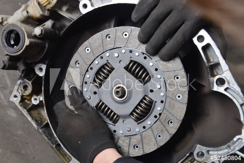
A clutch is a machine member used to connect a driving shaft to a driven shaft so that the driven shaft may be started or stopped at will, without stopping the driving shaft. The use of a clutch is mostly found in automobiles. A little consideration will show that in order to change gear or to stop the vehicle, it is required that the driven shaft should stop, but the engine should continue to run. It is, therefore, necessary that the driven shaft should be disengaged from the driving shaft. The engagement and disengagement of the shafts is obtained by means of a clutch which is operated by a lever.


Types of Clutches
Following are the two main types of clutches commonly used in engineering practice:
1.      Positive clutches
2.      Friction clutches.
Positive Clutches:
The positive clutches are used when a positive drive is required. The simplest type of a positive clutch is a jaw or claw clutch. The jaw clutch permits one shaft to drive another through a direct contact of interlocking jaws. It consists of two halves, one of which is permanently fastened to the driving shaft by a sunk key. The other half of the clutch is
movable and it is free to slide axially on the driven shaft, but it is prevented from turning relatively to its shaft by means of feather key. The jaws of the clutch may be of square type or of spiral type. A square jaw type is used where engagement and disengagement in motion and under load is not necessary. This type of clutch will transmit power in either direction of rotation. The spiral jaws may be left-hand or right-hand, because power transmitted by them is in one direction only. This type of clutch is occasionally used where the clutch must be engaged and disengaged while in motion. The use of jaw clutches are frequently applied to sprocket wheels, gears and pulleys. In such a case, the non-sliding part is made integral with the hub.

Friction Clutches:
A friction clutch has its principal application in the transmission of power of shafts and machines which must be started and stopped frequently. Its application is also found in cases in which power is to be delivered to machines partially or fully loaded. The force of friction is
used to start the driven shaft from rest and gradually brings it up to the proper speed without excessive slipping of the friction surfaces. In automobiles, friction clutch is used to connect the engine to the drive shaft. In operating such a clutch, care should be taken so that the friction surfaces engage easily and gradually bring the driven shaft up to proper speed. The proper alignment of the bearing must be maintained and it should be located as close to the clutch as possible. It may be noted that :
1. The contact surfaces should develop a frictional force that may pick up and hold the load with reasonably low pressure between the contact surfaces.
2. The heat of friction should be rapidly dissipated and tendency to grab should be at a minimum.
3. The surfaces should be backed by a material stiff enough to ensure a reasonably uniform distribution of pressure.

Types of Friction Clutches
Though there are many types of friction clutches, yet the following are important from the subject point of view:
1. Disc or plate clutches (single disc or multiple disc clutch),
2. Cone clutches, and
3. Centrifugal clutches.

Material for Friction Surfaces
The material used for lining of friction surfaces of a clutch should have the following characteristics:
1. It should have a high and uniform coefficient of friction.
2. It should not be affected by moisture and oil.
3. It should have the ability to withstand high temperatures caused by slippage.
4. It should have high heat conductivity.
5. It should have high resistance to wear and scoring.

Considerations in Designing a Friction Clutch
The following considerations must be kept in mind while designing a friction clutch.
1. The suitable material forming the contact surfaces should be selected.
2. The moving parts of the clutch should have low weight in order to minimize the inertia load, especially in high speed service.
3. The clutch should not require any external force to maintain contact of the friction surfaces.
4. The provision for taking up wear of the contact surfaces must be provided.
5. The clutch should have provision for facilitating repairs.
6. The clutch should have provision for carrying away the heat generated at the contact surfaces.
7. The projecting parts of the clutch should be covered by guard.


Monday, 1 April 2019

Historical Perspective of Development of Engines


Historical Perspective:
The objective of internal combustion engines (IC Engines) is the production of mechanical power from the chemical energy contained in the fuel. In internal combustion engines, as
distinct from external combustion engines, this energy is released by burning or oxidizing the fuel inside the engine. The fuel-air mixture before combustion and the burned products after combustion are the actual working fluids. The work transfers which provide the desired power output occur directly between these working fluids and the mechanical components of the engine. The internal combustion engines which are the subject of this blog are spark-ignition engines (sometimes called Otto engines, or gasoline or petrol engines, though other fuels can be used) and compression-ignition or diesel engines. Because of their simplicity, ruggedness and high power weight ratio, these two types of engine have found wide application in transportation (land, sea, and air) and power generation.
It is the fact that combustion takes place inside the work producing part of these engines that makes their design and operating characteristics fundamentally different from those of other types of engine. Practical heat engines have served mankind for over two and a half centuries.
 For the first 150 years, water, raised to steam, was interposed between the combustion gases produced by burning the fuel and the work-producing piston in- cylinder expander. It was not until the 1860s that the internal combustion engine became a practical reality. The early
engines developed for commercial use burned coal-gas air mixtures at atmospheric pressure there was no compression before combustion. J. J. E. Lenoir (1822-1900) developed the first mar-' ketable engine of this type. Gas and air were drawn into the cylinder during the first half of the piston stroke. The charge was then ignited with a spark, the pressure increased, and the burned gases then delivered power to the piston for the second half of the stroke. The cycle was completed with an exhaust stroke. Some 5000 of these engines were built between 1860 and 1865 in sizes up to six horsepower. Efficiency was at best about 5 percent. A more successful development-an atmospheric engine introduced in 1867 by Nicolaus A. Otto (1832-1891) and Eugen Langen (1833-1895)-used the pressure rise resulting from combustion of the fuel-air charge early in the outward stroke to accelerate a free piston and rack assembly so its momentum would generate a vacuum in the cylinder. Atmospheric pressure then pushed the piston inward, with the rack engaged through a roller clutch to the output shaft. Production engines, of which about 5000 were built, obtained thermal efficiencies of up to 11 percent. A slide valve controlled intake, ignition by a gas flame, and exhaust. To overcome this engine's shortcomings of low thermal efficiency and excessive weight, Otto proposed an engine cycle with four piston strokes: an intake stroke, then a compression stroke before ignition, an expansion or power stroke where work was delivered to the crankshaft, and finally an exhaust stroke. He also proposed incorporating a stratified-charge induction system, though this was not achieved in practice. His prototype four-stroke engine first ran in 1876. A comparison between the Otto engine and its atmospheric-type predecessor indicates the reason for its success: the enormous reduction in engine weight and volume. This was the breakthrough that effectively founded the internal combustion engine industry. By 1890, almost 50,000 of these engines had been sold in Europe and the United States. In 1884, an unpublished French patent issued in 1862 to Alphonse Beau de Rochas (1815-1893) was found which described the principles of the four-stroke cycle. This chance discovery cast doubt on the validity of Otto's own patent for this concept, and in Germany it was declared invalid. Beau de Rochas also outlined the conditions under which maximum efficiency in an internal combustion engine could be achieved.
These were:
1. The largest possible cylinder volume with the minimum boundary surface
2. The greatest possible working speed
3. The greatest possible expansion ratio
4. The greatest possible pressure at the beginning of expansion
The first two conditions hold heat losses from the charge to a minimum. The third condition
recognizes that the greater the expansion of the post combustion gases, the greater the work extracted. The fourth condition recognizes that higher initial pressures make greater expansion possible, and give higher pressures throughout the process, both resulting in greater work transfer. Although Beau de Rochas' unpublished writings predate Otto's developments, he never reduced these ideas to practice. Thus Otto, in the broader sense, was the inventor of the modern internal combustion engine as we know it today. Further developments followed fast once the full impact of what Otto had achieved became apparent. By the 1880s several engineers (e.g., Dugald Clerk, 1854-1913,; and James Robson, 1833-1913, in England and Karl Benz, 1844- 1929, in Germany) had successfully developed two-stroke internal combustion engines where the exhaust and intake processes occur during the end of the power stroke and the beginning of the compression stroke. James Atkinson (1846-1914) in England made an engine with a longer expansion than compression stroke, which had a high efficiency for the times but mechanical weaknesses. It was recognized that efficiency was a direct function of expansion ratio, yet compression ratios were limited to less than four if serious knock problems were to be avoided with the available fuels. Substantial carburetor and ignition system developments were required, and occurred, before high-speed gasoline engines suitable for automobiles became available in the late 1880s. Stationary engine progress also continued. By the late 1890s, large single-cylinder engines of 1.3-m bore fueled by low-energy blast furnace gas produced 600 BHP at 90 revlmin. In Britain, legal restrictions on volatile fuels turned their engine builders tower kerosene. Low compression ratio "oil" engines with heated external fuel vaporizers and electric ignition were developed with efficiencies comparable to those of gas engines (14 to 18 percent). The Hornsby-Ackroyd engine became the most popular oil engine in Britain, and was also built in large numbers in the United States America (USA). In 1892, the German engineer Rudolf Diesel (1858-1913) outlined in his patent a new form of internal combustion engine. His concept of initiating combustion by injecting a liquid fuel into air heated solely by compression permitted a doubling of efficiency over other internal combustion engines. Much greater expansion ratios, without detonation or knock, were now possible. However, even with the
efforts of Diesel and the resources of M.A.N. in Ausburg combined, it took five years to develop a practical engine. Engine developments, perhaps less fundamental but nonetheless important to the steadily widening internal combustion engine markets, have continued ever inch one more recent major development has been the rotary internal combustion engine. Although a wide variety of experimental rotary engines have been proposed over the years,' the first practical rotary internal combustion engine, the Wankel, was not successfully tested until 1957. That engine, which evolved through many years of research and development, was based on the designs of the German inventor Felix WankeL6* ' Fuels have also had a major impact on engine development. The earliest engines used for generating mechanical power burned gas. Gasoline, and lighter fractions of crude oil, became available in the late 1800s and various types of carburetors were developed to vaporize the fuel and mix it with air. Before 1905 there were few problems with gasoline; though compression ratios were low (4 or less) to avoid knock, the highly volatile fuel made starting easy and gave good cold weather performance. However, a serious crude oil shortage developed, and to meet the fivefold increase in gasoline demand between 1907 and 1915, the yield from crude had to be raised. Through the work of William Burton (1865-1954) and his associates of Standard Oil of Indiana, a thermal cracking process was developed whereby heavier oils were heated under pressure and decomposed into less complex more volatile compounds. These thermally cracked gasolines satisfied demand, but their higher boiling point range created cold weather starting problems. Fortunately, electrically driven starters, introduced in 1912, came along just in time. On the farm, kerosene was the logical fuel for internal combustion engines since it was used for heat and light. Many early farm engines had heated carburetors or vaporizers to enable them to operate with such a fuel. The period following World War I saw a tremendous advance in our understanding of how fuels affect combustion, and especially the problem of knock. The antiknock effect of tetraethyl lead was discovered at General ~otors,' and it became commercially available as a gasoline additive in the United States in 1923. In the late 1930s, Eugene Houdry found that vaporized oils passed over an activated catalyst at 450 to 480•‹C were converted to high quality gasoline in much higher yields than was possible with thermal cracking. These advances, and others, permitted
fuels with better and better antiknock properties to be produced in large quantities; thus engine compression ratios steadily increased, improving power and efficiency. During the past three decades, new factors for change have become important and now significantly affect engine design and operation. These factors are, first, the need to control the automotive contribution to urban air pollution and, second, the need to achieve significant improvements in automotive fuel consumption. The automotive air-pollution problem became apparent in the 1940s in the ~oAsng eles basin. In 1952, it was demonstrated by Prof. A. J. Haagen-Smit that the smog problem there resulted from reactions between oxides of nitrogen and hydrocarbon compounds in the presence of sunlight.' In due course it became clear that the J automobile was a major contributor to hydrocarbon and oxides of nitrogen emissions, as well as the prime cause of high carbon monoxide levels in urban areas. Diesel engines are a significant source of small soot or smoke particles, as well as hydrocarbons and oxides of nitrogen. As a result of these developments, emission standards for automobiles were introduced first in California, then nationwide in the United States, starting in the early 1960s. Emission standards in Japan and Europe, and for other engine applications, have followed. Substantial reductions in emissions from spark-ignition and diesel engines have been achieved. Both the use of catalysts in spark-ignition engine exhaust systems for emissions control and concern over the toxicity of lead antiknock additives have resulted in the reappearance of unleaded gasoline as a major part of the automotive fuels market. Also, the maximum lead content in leaded gasoline has been substantially reduced. The emission-control requirements and these fuel developments have produced significant changes in the way internal combustion engines are designed and operated. Internal combustion engines are also an important source of noise. There are several sources of engine noise: the exhaust system, the intake system, the fan used for cooling, and the engine block surface. The noise may be generated by aerodynamic effects, may be due to forces that result from the combustion process, or may result from mechanical excitation by rotating or reciprocating engine components. Vehicle noise legislation to reduce emissions to the environment was first introduced in the early 1970s. During the 1970s the price of crude petroleum rose rapidly to several times its cost (in real terms) in 1970, and concern built up regarding the longer-term availability of petroleum. Pressures for substantial improvements in internal combustion engine efficiency (in all its many applications) have become very substantial indeed. Yet emission-control requirements have made improving engine fuel consumption more difficult, and the removal and reduction of lead in gasoline has forced spark-ignition engine compression ratios to be reduced. Much work is being done on the use of alternative fuels to gasoline and diesel. Of the non-petroleum-based fuels, natural gas, and methanol and ethanol (methyl and ethyl alcohols) are receiving the greatest attention, while synthetic gasoline and diesel made from shale oil or
coal, and hydrogen could be longer-term possibilities. It might be thought that after over a century of development, the internal combustion engine has reached its peak and little potential for further improvement remains. Such is not the case. Conventional spark-ignition and diesel engines continue to show substantial improvements in efficiency, power, and degree of emission control. New materials now becoming available offer the possibilities of reduced engine weight, cost, and heat losses, and of different and more efficient internal combustion engine systems. Alternative types of internal combustion engines, such as the stratified charge (which combines characteristics normally associated with either the spark-ignition or diesel) with its wider fuel tolerance, may become sufficiently attractive to reach large-scale production. The engine development opportunities of the future are substantial. While they present a formidable challenge to automotive engineers, they will be made pos- &le in large part by the enormous expansion of our knowledge of engine processes which the last twenty years has witnessed.