Combustion in SI Engine
The combustion process
is defined as a rapid chemical reaction between the H2 and C with
oxygen in the air and liberates energy in the form of heat. It is not the
purpose of this article to study the combustion of fuel in details as it is
very complicated phenomenon. The purpose of this article is just to introduce
the combustion in SI engines and effects of different parameters on the
combustion and ultimately the effects on engine performance.
It is absolutely
essential to burn the fuel supplied completely for the economical working of
the engine and also for the safety of the engine and environment. Therefore,
the mixture supplied to the engine should possess A:F ratio otherwise,
combustion cannot be initiated or if initiated it cannot be sustained. In
addition to this, there must be some means to initiate the combustion and the
generated flame should be able to propagate through the mixture and burn the
mixture completely.
It is known fact that
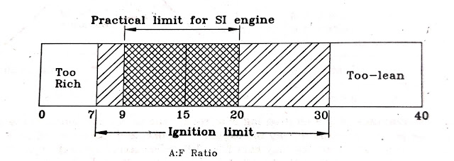
the fuel vary with A:F ratio cannot be burned. There is a ignition limit
for any fuel to start the combustion and sustain it till the complete fuel
burns by the flame generated with spark plug. In addition to this, the
temperature of the mixture to initiate the ignition is equally important. It is
also known that the flame will propagate if the temperature of the burnt gases
exceeds 1500 K for SI engine fuels. The ignition limits of hydrocarbon fuel
when temperature of mixture reaches to 1500 K are shown in the figure given
below:
The upper and lower
limit of A:F ratio for ignition depends upon the temperature of a particular
fuel. The limit becomes wider at higher temperatures because of higher reaction
rate and higher thermal diffusivity coefficients of the mixture. Therefore, it
is very essential to see that the A:F ratio of the mixture supplied to the
engine should lie in the practical limit as shown in the figure.
Stages of Combustion in
SI Engines:
It is assumed that the
heat is added instantaneously of constant volume in the ideal air-cycle of SI
engine. To achieve this, the burning of the fuel in the SI engine should be
instantaneous. In actual engines, combustion occurs over a finite period of time
as the flame starting around the spark plug has to propagate through the entire
mixture of the air and fuel.
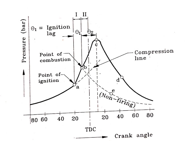
The pressure variation
in the SI engine combustion chamber during the crank rotation is shown in the
figure given below. This is really an unfolded p-v diagram.
The ignition is timed
to take place at the point ‘a’ but the burning commences only at the point ‘b’.
The time interval between these two points is known as “Ignition lag”.
The major disadvantage of the ignition lag is that it reduces the power
developed. If the ignition lag is too long, the peak pressure occurs during the
expansion stroke, and therefore full advantage of expansion is not achieved.
All consideration should be taken into account in the design of the combustion
chamber and selecting the fuel used to reduce the ignition lag.
The theoretical diagram
of combustion is shown in the figure:
But actual process
differs from theoretical as instant combustion is not possible as shown by bc.
The combustion to start takes small time after giving the spark as the
surrounding mixture is to be heated up to ignition temperature and then formed
nucleus of flame starts propagating through the surrounding mixture.
The pressure variation
in the engine with respect to the crank angle is shown in the figure. There are
mainly three stages of combustion in SI engines as shown in the figure.
1.
First Phase:
This
phase is considered between the point of ignition and point of combustion. As
shown in figure, ignition is timed at the point ‘a’ and combustion starts at
the point ‘b’. The period of ignition lag is very small and lies between
0.00015 to 0.002 seconds. An ignition lag of 0.002 sec corresponds to 350 crank
rotation when the engine is running at 3000 RPM and crank angle required (which
is also known as angle of advance) increases with an increase in engine speed.
2.
Second Phase:
Once
the flame formed at the point ‘b’, it should be self-sustained and must to able
to propagate through the mixture. This is possible when the rate of heat
generation by burning the surrounding mixture of the flame nucleus must be
higher than the heat lost by the flame to the surrounding. As the difference
between heat generation and heat lost is higher, the rate of flame propagation
is higher and complete combustion will occur earliest possible this is most
desirable requirements of combustion in SI engines. The propagation of flame
also depends upon the flame temperature as well as temperature and density of
the surrounding mixture as its propagation is directly proportional to these
factors. Weak spark and low compression ratio (as density of mixture is less)
gives low propagation of the flame.
After
the point ‘b’, the flame propagation is abnormally low at the beginning as heat
loss is more than the heat generated. Therefore, the pressure rise is also slow
as mass of mixture burned is small. Therefore, it is necessary to provide angle
of advance 30 to 350 if the peak pressure is to be attained 5 to 100
after TDC.
After
the point ‘c’, the pressure starts falling due to the fall in the rate of heat
release when the flame reaches the wall in the last part of combustion and
cannot compensate for its fall due to gas expansion, and heat transfer to the
walls.
The
time required for the flame to travel 95% of the chamber length with respect to
speed of the engine is shown in the figure below:
It
is obvious, the crank angle required for 95% travel increases with increasing
RPM (the time available is decreased), therefore, if the combustion is to be
completed at point ‘c’, the angle of advance must be increased with increasing
RPM. The flame speed increases with increasing RPM because of increase in
turbulence of the mixture.
The
time required for the crank to rotate through an angle Ѳ2 is known
as combustion period during which the propagation of the flame takes place.
The
stage I and II are not entirely distinct. The starting point of stage II is
measurable as rise in pressure can be seen on p- Ѳ diagram. This is the point
where the line of combustion departs from the line of compression.
3.
Third Phase:
Although
the point ‘c’ represents the end of flame travel, it does not assure the
complete combustion of fuel. In this case, the combustion still continues after
attaining the peak pressure also and this combustion is known as After
Burning. This is continued throughout the expansion stroke. This
generally happens when the rich mixture is supplied to the engine.


No comments:
Post a Comment