Monday, 24 June 2019

Stages of Combustion in SI Engines


Combustion in SI Engine
The combustion process is defined as a rapid chemical reaction between the H2 and C with oxygen in the air and liberates energy in the form of heat. It is not the purpose of this article to study the combustion of fuel in details as it is very complicated phenomenon. The purpose of this article is just to introduce the combustion in SI engines and effects of different parameters on the combustion and ultimately the effects on engine performance.

Combustion Chamber


It is absolutely essential to burn the fuel supplied completely for the economical working of the engine and also for the safety of the engine and environment. Therefore, the mixture supplied to the engine should possess A:F ratio otherwise, combustion cannot be initiated or if initiated it cannot be sustained. In addition to this, there must be some means to initiate the combustion and the generated flame should be able to propagate through the mixture and burn the mixture completely.
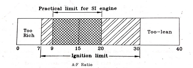
It is known fact that the fuel vary with A:F ratio cannot be burned. There is a ignition limit for any fuel to start the combustion and sustain it till the complete fuel burns by the flame generated with spark plug. In addition to this, the temperature of the mixture to initiate the ignition is equally important. It is also known that the flame will propagate if the temperature of the burnt gases exceeds 1500 K for SI engine fuels. The ignition limits of hydrocarbon fuel when temperature of mixture reaches to 1500 K are shown in the figure given below:

Ignition Limit

The upper and lower limit of A:F ratio for ignition depends upon the temperature of a particular fuel. The limit becomes wider at higher temperatures because of higher reaction rate and higher thermal diffusivity coefficients of the mixture. Therefore, it is very essential to see that the A:F ratio of the mixture supplied to the engine should lie in the practical limit as shown in the figure.

Stages of Combustion in SI Engines:
It is assumed that the heat is added instantaneously of constant volume in the ideal air-cycle of SI engine. To achieve this, the burning of the fuel in the SI engine should be instantaneous. In actual engines, combustion occurs over a finite period of time as the flame starting around the spark plug has to propagate through the entire mixture of the air and fuel.
The pressure variation in the SI engine combustion chamber during the crank rotation is shown in the figure given below. This is really an unfolded p-v diagram.

p-v diagram

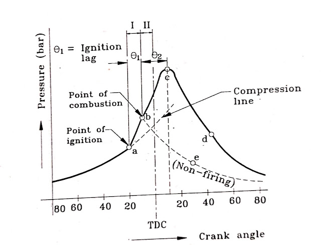
The ignition is timed to take place at the point ‘a’ but the burning commences only at the point ‘b’. The time interval between these two points is known as “Ignition lag”. The major disadvantage of the ignition lag is that it reduces the power developed. If the ignition lag is too long, the peak pressure occurs during the expansion stroke, and therefore full advantage of expansion is not achieved. All consideration should be taken into account in the design of the combustion chamber and selecting the fuel used to reduce the ignition lag.


The theoretical diagram of combustion is shown in the figure:

Theoretical diagram of Combustion

But actual process differs from theoretical as instant combustion is not possible as shown by bc. The combustion to start takes small time after giving the spark as the surrounding mixture is to be heated up to ignition temperature and then formed nucleus of flame starts propagating through the surrounding mixture.

The pressure variation in the engine with respect to the crank angle is shown in the figure. There are mainly three stages of combustion in SI engines as shown in the figure.

Pressure Variation with Crank angle

1.      First Phase:
This phase is considered between the point of ignition and point of combustion. As shown in figure, ignition is timed at the point ‘a’ and combustion starts at the point ‘b’. The period of ignition lag is very small and lies between 0.00015 to 0.002 seconds. An ignition lag of 0.002 sec corresponds to 350 crank rotation when the engine is running at 3000 RPM and crank angle required (which is also known as angle of advance) increases with an increase in engine speed.

2.      Second Phase:
Once the flame formed at the point ‘b’, it should be self-sustained and must to able to propagate through the mixture. This is possible when the rate of heat generation by burning the surrounding mixture of the flame nucleus must be higher than the heat lost by the flame to the surrounding. As the difference between heat generation and heat lost is higher, the rate of flame propagation is higher and complete combustion will occur earliest possible this is most desirable requirements of combustion in SI engines. The propagation of flame also depends upon the flame temperature as well as temperature and density of the surrounding mixture as its propagation is directly proportional to these factors. Weak spark and low compression ratio (as density of mixture is less) gives low propagation of the flame.
After the point ‘b’, the flame propagation is abnormally low at the beginning as heat loss is more than the heat generated. Therefore, the pressure rise is also slow as mass of mixture burned is small. Therefore, it is necessary to provide angle of advance 30 to 350 if the peak pressure is to be attained 5 to 100 after TDC.
After the point ‘c’, the pressure starts falling due to the fall in the rate of heat release when the flame reaches the wall in the last part of combustion and cannot compensate for its fall due to gas expansion, and heat transfer to the walls.
The time required for the flame to travel 95% of the chamber length with respect to speed of the engine is shown in the figure below:

Crank angle with engine speed

It is obvious, the crank angle required for 95% travel increases with increasing RPM (the time available is decreased), therefore, if the combustion is to be completed at point ‘c’, the angle of advance must be increased with increasing RPM. The flame speed increases with increasing RPM because of increase in turbulence of the mixture.
The time required for the crank to rotate through an angle Ѳ2 is known as combustion period during which the propagation of the flame takes place.
The stage I and II are not entirely distinct. The starting point of stage II is measurable as rise in pressure can be seen on p- Ѳ diagram. This is the point where the line of combustion departs from the line of compression.
3.      Third Phase:
Although the point ‘c’ represents the end of flame travel, it does not assure the complete combustion of fuel. In this case, the combustion still continues after attaining the peak pressure also and this combustion is known as After Burning. This is continued throughout the expansion stroke. This generally happens when the rich mixture is supplied to the engine.

Monday, 17 June 2019

Lubricating Systems


Engine Friction and Lubrication (Part IV)
The main function of lubricating system is to provide sufficient and cool filtered oil to all the moving parts of an engine. The systems are classified as splash lubricating system and pressure feed lubricating system.

Engine


We have discussed about basic of Engine friction and lubrication in previous blogs. The link for part I, II and III are provided below.
1.      Splash Lubrication System
The arrangement of the system is shown in the figure below:

Splash Lubricating System

This method generally used for vertical engines with a closed crankcase. The sump is located at the bottom of the crankcase. When the engine crankshaft rotates, the big end of the connecting rod splashes oil by centrifugal action. The connecting rod big end has a hollow pipe called a scoop which is fitted to the bearing cap and pointed towards the direction of the rotation of the crank shaft. The lubricating oil passing through the scoop, lubricate the big end bearing and gudgeon pin bearing. All other parts are lubricated by the splash. Excess oil is collected in the troughs located as shown in the figure and is provided with overflows and collected in the main sump. The level of the oil in trough is maintained constant. The dripping from the cylinders is also collected in the sump. The oil from the sump is recirculated with the help of the pump as shown in figure.
The inability to regulate the quantity of oil splashed against the cylinder wall or inability to keep the oil from getting past the piston head into the combustion chamber, burning with the fuel and passing out with exhaust gases are limitations of this system.

2.      Pressure Feed Lubricating System:
All modern car and bus engines are lubricated by high pressure feed system as shown in the figure given below:

Pressure Feed Lubricating System

Such a system supplies oil under pressure (2 to 5 bar) directly to the connecting rod bearings, to the camshaft bearings, to the valve gear and to the camshaft drive. Indirect supplies reach the cylinder walls, the gudgeon pin, the distributor and pump drives.
Oil is carried in the sump, a deep tray which closes the bottom of the crankcase and is circulated by the gear pump which sucks from the sump through a strainer as shown in the figure. The pump delivery pressure is controlled by a relief valve and the oil passes through a very fine filter before it reaches the main distributor gallery. From the various bearings, surfaces and gears, the oil simply drains back into the sump.
After lubricating the big end bearings, the oil is fed to the gudgeon pins through the oil way in the connecting rod and further squirted into the cylinder wall.

3.      Charge Lubrication System
This is the simplest method of lubrication and does not require oil filter and oil pump. In this system, the lubricating oil is pre-mixed with the petrol therefore the fuel carries the lubricating oil in the cylinder which helps for lubricating the piston and cylinder. Most of the oil burns with the fuel due to high temperature and burnt oil is carried with the exhaust gases. The lubricating oil cannot be recovered in this system.
This type of lubrication is generally used for two stroke spark ignition engines of scooter and motorcycle. The quantity of lubricating oil mixed with the petrol is 3 to 6% of petrol.
The advantages of this system are listed below:
a.      It does not require separate lubricating system so it is most economical.
b.      There is no risk of failure of lubricating system.
c.      The lubricating oil supplied is regulated at various loads and speeds by the increased fuel flow.
The carbon deposits due to the burning of the oil on the spark plug and on other parts and non-recovery of the oil used are the main disadvantages of this system.
The lubricating system is also classified as wet-sump lubrication and dry sump lubrication system.
1.      Wet Sump Lubricating System:
The arrangement is shown in the figure below:
Wet Sump Lubricating System

This is called wet sump as sump is always full of oil. The working is just similar to the pressure feed lubricating system.
Oil is drawn from the sump by an oil pump through an oil strainer. A pressure relief valve is provided which automatically maintains the delivery pressure constant. If the pressure exceeds than the predetermined pressure, the valves opens and allows some of the oil to return to the sump and relives the oil pressure in the system. The oil from the pump goes to the bearings and part of it passes through a filter which removes solid particles from the oil. As all the oil is not passed through the filter, the system is known as by-pass filtering system. Advantages of this system are that a clogged filter will not restrict the flow of oil to the engine.

2.      Dry Sump Lubricating System:
The dry sump lubricating system is shown in the figure given below:

Dry Sump Lubricating System

This is known as dry-sump as the sump does not contain oil and all the oil required for lubrication remains in the circulation only. High speed racing cars and military jeeps use this type of lubricating system as the oil in the wet sump is subjected to large back and forth acceleration.
An auxiliary tank is used to supply the oil to the main bearings with the help of the pump. The oil returns back to tray and then returned back to the auxiliary tank by scavenging pump, the capacity of which is always 20 to 30% more than the pressure pump to avoid flooding of the crankcase.
If the filter is clogged, the pressure relief valve opens permitting oil to flow bypassing the filter and reaches the supply tank. The oil is then circulated to the bearings from the supply tank. A separate oil cooler is used to cool the oil to remove the heat from the oil as heating of oil is rapid because of rapid circulation of oil and high speed of the engine.

Sunday, 16 June 2019

Engine Friction and Lubrication


Engine Friction and Lubrication (Part 3)

In Previous blogs, we have discussed about basic of Engine Friction, Lubrication, and Grading of lubricating oil, grease lubrication and additives. Here, in this blog, we will discuss about Effect of Engine Variables on Friction.
Lube


Click on the link below for the part I and II on Engine Friction and Lubrication.

Effect of Engine Variables on Friction:
There are many geometrical parameters and physical parameters which are responsible for the frictional losses. Those parameters are considered in this blog.

a.      Stroke to Bore Ratio (L/D):
Lower L/D ratio tends to decrease IMEP. Its lower value reduces the friction losses as the surface area decreases with decreasing L/D ratio with the same value of the stroke volume as shown in the figure given below:

L/D

b.      Cylinder size and number of cylinders:
A smaller number of larger cylinders are preferred as the fuel economy is higher. This is because the proportion between piston area and its circumference area is reduced. Figure given below shows the effect of engine cylinders on the variation of friction for the same piston displacement. It is obvious from the figure that 4 and 6 cylinder engines are more efficient than 8 cylinder engine as fuel economy is concerned.

Cylinder size and Friction


c.      Compression Ratio:
With an increase in compression ratio, IMEP increases as well as MEPF by friction also increases but with a lower rate, so the mechanical efficiency of the engine increases with increasing compression ratio.

Compression Ratio


d.      Engine Speed:
The friction loss increases with an increase in speed of the engine as rubbing between cylinder and piston occurs more times as engine speed increases. The best method to improve mechanical efficiency with higher speed engine to increase the number of cylinders. The variation of frictional mean effective pressure (MEPf) varies linearly with RPM and The effect of speed on different types of frictional losses are also shown in the figure below:

RPM and Friction

e.      Engine Load:
As the load on the engine increases, the IMEP also increases and friction loss also increases. However this increase in friction loss is compensated by decrease in viscosity of the lubricating oil due to higher temperature resulting from increases load.

f.       Cooling water temperature:
The rise in cooling water temperature reduces the frictional loss as the viscosity of oil at higher temperature is lower which reduces the friction loss.
The starting friction loss is higher as the water and oil will be at the same temperature and oil viscosity is higher. This also adds rapid engine wear. The effect of cooling temperature on friction loss is shown in figure below:

Coolant and Friction

g.      Oil Viscosity:
Higher is oil viscosity, the higher will be the pressure losses. As the oil temperature increases, the viscosity decreases and frictional loss also upto certain temperature of the oil as shown in the figure below:

Viscosity and Friction

If the temperature goes higher than 1000C, again friction loss increases as local film is destroys and results in metal to metal contact.

h.      Number of Piston Rings:
Number of rings and frictionThe effect of the number of piston rings on the friction is not significant as the selection depends on the size of the engine, lightness required and material used for rings. However, the effect is shown in the figure given below and it is obvious that generally 3 rings provide best fuel economy.

The friction force by the rings occurs due to ring tension and due to gas pressure force behind the ring.
Also, the figure given below shows the cylinder gas pressure behind the top ring. Because of ring tension, the ring pressure against the cylinder valve results in frictional losses. In addition to the ring tension, the gas
Piston Rings Arrangement
pressure behind the ring also causes friction loss. The pressure acting on the top piston ring is as high as gas pressure on the piston but it is much lower for other piston rings. For oil ring, no gas pressure acts on it.
In this blog, we discussed about the Effect of Engine Variables on Friction. Lubricating Systems will be discussed in next part of this blog.

Friday, 14 June 2019

Fuel Supply to SI Engines


Fuel Supply to SI Engines (Carburetion):
Introduction:
The process of preparing air-fuel mixture in SI engine outside the engine cylinder is known as Carburetion. The device used for this purpose is known as Carburetor.
Carburetor

In petrol engines, the air and fuel is mixed outside the engine and partly evaporated mixture is supplied to the engine. The fuels such as petrol, benzol and alcohol used in SI engine vaporizes easily if injected in the flow of air, therefore, the engine suction is sufficient to create the air flow and fuel injected easily evaporates. The oil fuels which are used in CI engines do not vaporize easily. Therefore, a separate injection system is used. These systems will be discussed in the next blog.
The vaporization process of the fuel in the current of air depends mainly upon, the physical properties of fuel, the temperature of incoming air in the intake manifold, the pressure difference causing the flow of fuel in the air, design of intake manifold and the time available for evaporation.
The simple arrangement of the mixture supply to SI engine is shown in the figure below:


During the suction, the air is sucked as vacuum is created inside the engine cylinder. The fuel is injected in the air from the carburetor and a mixture is supplied to the engine cylinder.
It is desirable to have a complete vaporized mixture in the engine cylinder but some of the large droplets may reach the cylinder in the form of liquid and they are mixed and vaporized during the compression stroke.
The time available for atomization, mixing and vaporization is so small, (0.02 second when engine is running at 3000 RPM) the design of the system becomes more difficult. The temperature is one of the factors which accelerate vaporization but this would reduce the power output due to reduction in mass flow.
The design of carburetor is difficult and complicated as the requirements by the engine for A:F ratio vary from 1:1 to 15:1 under different operating conditions. Therefore, the design of different components and devices incorporated in the carburetor to fulfill all the above mentioned requirements will be discussed in subsequent articles.
Fuel Supply system to Automobile and Fuel Pumps:
The general arrangement of fuel supply system to SI engine used in automobile is shown in figure below:
General arrangement of petrol supply system


Generally on four wheeler automobile, the fuel tank is located away from the engine to avoid vapor lock and fire hazard. The fuel is pumped with the help of a petrol pump from the storage tank to the carburetor as the tank level is always below the level of the float chamber of the carburetor, the pressure developed should be just sufficient to overcome the frictional losses passing through the filter and pipe line carrying the petrol from the tank to the carburetor float chamber.
Types of Petrol pump:
There are two types of petrol pumps commonly used in practice as Mechanical pump and Electrical pump.
a.      Mechanical Petrol Pump:
It is located near the engine as it is operated by the engine itself. It is mounted on the side of the crank case and operated by an eccentric on the cam shaft as shown in the figure below:

Mechanical Fuel Pump

This consists of a chamber divided into two compartments as shown in the figure. The top portion contains a filter and sediment boul and has two spring loaded valves to control the flow of petrol. The lower portion contains a spring which regulated the pressure of the petrol supply and an operating link and rocker arm driven by the cam shaft. The diaphragm fitted as shown in the figure is alternately pulled down by the link and then pushed up by the spring.
The pump lever is made of two parts in such a way that it only pulls the diaphragm down and then it is taken up by the spring as the lever action goes out.
As the eccentric (mounted on the cam shaft) pushes the lever towards the right, the rocker arm pushes the push rod and the diaphragm down creating a vacuum inside the down chamber of the pump. This vacuum is sufficient to open the inlet valve and sucks the petrol. As the eccentric goes out of the action, the push rod and the diaphragm is pushed up by the spring action and pressurizes the fuel taken in. This pressure (1.1 to 1.3 bar) is sufficient to open the delivery valve and supply the petrol to the carburetor. As this is done, the lever comes into the operation. Once more to pull the diaphragm down and suck the petrol again and operation is repeated.
The filter is covered by a glass boul as shown in the figure so that the accumulated sediment can be seen and boul can be removed easily for cleaning purposes.
The double lever arrangement is essentially used because, if it were in single piece, the lever would operate the diaphragm and pump the petrol continuously to the carburetor even the carburetor float is full. This would cause the float chamber to overflow. Double lever arrangement overcomes this difficulty.
The mechanical pump is highly reliable but it operates only when the engine is running. A hand lever, used for priming the pump, operated in the same manner as the pump lever pulls the diaphragm down when operated, drawing the petrol in.
The mechanical pump is always subjected to heat as located near the engine and can cause vapor lock although insulated.
The diaphragm may become porous after a long service and in such case it must be changed immediately to prevent the petrol leaking into the engine and mixing with the lubricating oil.

b.      Electric Pump:
The electric pump works on the same principle as mechanical pump except that the diaphragm is operated by a solenoid instead of by a cam shaft.
The arrangement of the pump is shown in the figure below:

Electric Fuel Pump

It consists of an electromagnetic coil which is connected to the battery through a contact points. These contact points are separated by a pull rod which is also connected to the diaphragm by a diaphragm spring.
The advantages of electric pump over mechanical are:
1.      It can be started without starting the engine. It starts as soon as the ignition circuit is switched on.
2.      It is not affected by the engine heat and totally free from vapor lock.
More details about the Fuel Supply to SI Engines will be discussed in next coming blog. Air fuel mixture and mixture requirements will be discussed.

Wednesday, 12 June 2019

The Biggest and most Powerful Nuclear Weapons ever Built


Nuclear Weapon (Tsar Bomb)
A Nuclear weapon (also known as nuclear bomb, nuke, atomic bomb) is an extremely explosive device that derives its destructive force from nuclear reactions, either fission or fusion or combination of both. Nuclear weapons technology was developed during 1930s and 1940s. The first nuclear bombs were detonated during World War II over Hiroshima and Nagasaki in August 1945. The atomic bomb contained only about 64 kg (140 pounds) of highly enriched Uranium, released energy equaling about 15 kilotons of chemical explosive. The blast immediately produced a strong shock wave, enormous amounts of heat and lethal ionizing radiation. The devastating power of bombs dropped on Japan forced the surrender of the Japanese.
Nuke Bomb


Since then, controlling the proliferation of nuclear weapons has been an important issue in international relations and the two detonations in Japan remained the only ever usage in warfare till now.
Tsar Bomb:
The RDS-220 Hydrogen bomb, also known as the Tsar Bomba, is the biggest and most powerful thermonuclear bomb ever made. It was tested by the Soviet Union on 30 October 1961 over Novaya Zemlya Island in the Russian Arctic Sea. The Tsar bomb was air dropped by a Tu-95 bomber using huge fall-retardation parachute. The detonation occurred 4 km above the ground producing a yield of 50 Mt, which is supposed to be equivalent to the explosive power from the simultaneous detonation of 3,800 Hiroshima bombs.
Tsar Bomb contained three stages, unlike normal thermonuclear weapons that explode in just two stages. While the addition of third stage increased the explosive power of the thermonuclear, the bomb’s actual yield of 100 Mt was reduced by 50% to limit the radioactive dust. According to initial data, the Tsar bomb had a nuclear yield of 58.6 Mt (245 PJ), and was overestimated at values all the way up to 75 Mt (310 PJ). 

Some major data of explosion:
Ø  The 8 km fireball reached nearly as high as the altitude of the release plane and was visible at almost 1,000 km away from where it ascended,
Ø  The mushroom cloud was about 67 km (42 mi) high,
Ø  The cap of the mushroom cloud had a peak width of 95 km and its base was 40 km wide,
Ø  Its seismic body wave magnitude was estimated at 5-5.25,
Ø  The bomb, weighing 27 metric tons, was so large (8 meter long by 2.1 meter in diameter),
Ø  The bomb was attached to an 800 kilogram, 1600 square meter parachute, which gave the release and observer planes time to fly about 45 kilometers away from ground zero, giving them a 50% chance of survival.

List of Most Powerful Nuclear Weapons:
a.      B41 nuclear bomb – 25 Mt
b.      TX-21 “Shrimp” (Castle Bravo) – 14.8 Mt
c.      MK-17/EC-17 – 10 Mt to 15 Mt
d.      MK 24/B-24 – 10 Mt to 15 Mt
e.      Ivy Mike H-Bomb – 10.4 Mt
f.       Mk-36 nuclear bomb – 10 Mt
g.      B53 (MK-53) – 9 Mt
h.      MK-16 (TX-16/ EC-16) nuclear bomb – 7 Mt
i.        MK-14/ TX-14 – 6.9 Mt


Saturday, 8 June 2019

Adiabatic Engines, Concept and Performance Analysis

Introduction:
Many development programs have been arranged in many countries during the last 20 years to improve the efficiency of the IC engines, particularly diesel engines. Adiabatic engine is one of the program to develop an engine with higher efficiency.


Adiabatic Engine

The feature of an adiabatic engine is that the combustion takes place in an insulated cylinder and the engine works at a considerably higher temperature than conventional engines. This reduces the loss of heat going to cooling water. In addition to this, the part of the heat carried by exhaust gases can also be converted into work passing through a turbine. This further reduces the weight of the system. The use of low conductivity material for cylinder wall increases wall temperature which increases the danger of knocking in SI engines but decreases knocking tendency in CI engine. Therefore, this concept is considered only for diesel engine.
Concept of Adiabatic Engine:
In thermodynamics, a adiabatic process is defined as a no heat loss process. An adiabatic engine is a system where Q=0, when the system is fully functional. Generally, it is difficult to have adiabatic engine in practise. However, an adiabatic engine has no conventional cooling and strives to minimise heat loss. The adiabatic engine combustion chamber is made of material which allows the operation of the engine with minimum heat loss. Fundamentally, the adiabatic engine is more efficient than conventional diesel engine because it converts the fuel heat into additional useful output.
The hot or insulated high temperature components include piston, cylinder head, valves, cylinder liner and exhaust manifold. Additional power and improved thermal efficiency from an adiabatic engine are possible because, thermal energy, normally lost to the cooling water and exhaust gases, is converted into useful power through the use of high temperature materials and a small gas turbine.
Lubrication of Adiabatic Engines:
The high temperature lubricant is the major problem in the development of adiabatic engine. The ceramic liner temperature reaches to 5000C against the conventional engine liner temperature of 2000C. The lubricant used must resist such high temperature and maintain the viscosity property required for low friction.
The following methods can be used:
i.                    Gas lubricated piston-ring-liner combination.
ii.                 Unlubricated ceramic roller bearings for the wrist pin, crank pin and main bearings.
iii.               Solid lubricant coating for gears, valve guides, rocker arm and push rod assembly.
The following synthetic oils are suggested for lubrication of hot engine surfaces:
i.                    Ester + synthetic chain,
ii.                 Polyolester + synthetic HC
Performance of Adiabatic Engines:
The performance of the engine mostly depends upon the effective insulation used. An increase in engine wall temperature reduces the heat loss through the walls while increasing the exhaust gas energy loss.
For engines, where the exhaust gas is also used to develop power, there is an improvement in thermal efficiency of the engine. Calculations have shown that 40% reduction in heat flow through the cylinder wall increases the thermal efficiency by 2%.
The lower volumetric efficiency resulting from high degree of insulation has negative effect on power output which can be overcome by turbo-charging. The frictional losses were increased because of lower viscosity of the lubricating oil at elevated temperatures.
The adiabatic engine is more suitable for bi-fuel operation with alcohols which have high latent heat of vaporisation. The hot walls of combustion chamber help for better and quick vaporisation. This makes it possible to utilize a higher percentage of alcohol in an adiabatic engine compared to a normal dual-fuel engine.