Introduction:
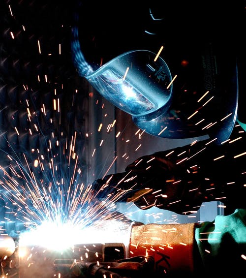
Welding is a
process of joining similar or dissimilar metal by fusion with or without the
application of pressure and with or without use of filler rod. Fusion is
obtained by heat. The heat may be obtained from electric arc, electric
resistance, chemical reaction, friction or radiant energy. The result is
continuity of the homogenous material of the composition and the
characteristics of two parts which are being joined together.
Welding process
has the wide application. The future of any new metal may depend upon how far
it would lend itself to fabrication by welding. Two metals parts of same type
can be joined together and the joint is strong as well. We can see different
application around us like the grills, corridor barriers, gates, etc.
Objectives:
The main objectives of the welding process are as follows:
i) To know the various aspects of welding.
ii) To know the different tools and raw materials and
different kinds of welding.
iii) To know how to weld and to know the different ways of
welding.
Applications:
a.
Automobile constructions
b.
Railroad equipments
c.
Construction of ships
d.
Aircraft construction
e.
Building construction
f.
Bridge construction
g.
Pressure vessels
h.
Storage tanks
i.
Piping and pipe lines
j.
Fabrication of jigs, fixture and machine tools
k.
Repair of broken and damaged parts
l.
Household materials
m.
Material handing equipments etc..
CLASSIFICATION OF WELDING
In general, various welding and allied process are
classified as follows:
- Gas welding
v Air acetylene welding
v Oxy-acetylene welding
v Oxy-hydrogen welding
v Pressure gas welding
- Arc welding
v Carbon arc welding
v Metal arc welding
v Flux cored arc welding
v Submerged arc welding
v Gas tungsten arc
welding(TIG)
v Gas metal arc welding(MIG)
v Plasma arc welding
v Electro slag arc
welding
v Electro gas arc welding
v Stud arc welding
- Resistance welding
v Spot welding
v Seam welding
v Projection welding
v Resistance butt welding
v Flash butt welding
v Percussion welding
v High frequency
resistance welding
- Solid state
welding
v Cold welding
v Diffusion welding
v Explosive welding
v Forge welding
v Friction welding
v Hot pressure welding
v Roll welding
v Ultra sonic welding
- Thermo
chemical welding process
v Thermit welding
v Atomic hydrogen welding
- Radiant
energy welding process
v Electron beam welding
v Laser beam welding
i.
ARC WELDING
Arc welding is
the most extensively employed method of joining metal part. Here the source of
heat is an electric arc.
The arc column
is generated between an anode, which is the positive pole of DC power supply,
and the cathode, the negative pole when this two conductor of an electric are
brought together and separated for a small distance ( 2 to 4mm) such that
current continue to flow through the part of ionized particle(gaseous medium)
called plasma, an electric arc is formed. The ionized gas column act as high
resistance conductors that enable more ions to flow from anode to cathode. Heat
is generated as the ions strike the cathode.
1.
ARC WELDING EQUIPMENT
The
most commonly used equipment for arc welding consist of the following:
i.
AC or DC machine
ii.
electrode holder
iii.
cables, cables connectors
iv.
cables lug
v.
chipping hammer
vi.
earthing clamps
vii.
wire brush
viii.
helmet
ix.
safety goggles
x.
hand gloves
xi.
aprons, sleeves
xii.
electrode
a. FLUX SHIELDED
ARC WELDING
In this method,
a rod of carbon is used as a negative electrode and the work being welded as a
positive. The arc produced between these two electrodes heats the metal to the
melting temperature. The reason to use carbon rod as negative electrode is that
less heat will be generated at the electrode tip than that at the workpiece,
and carbon from the electrode will not fuse and mixed up with the job.
TOOL USED:
i.
Arc welding Machine
ii.
Electrode for welding
iii.
Earthing Clamp
iv.
Chipping Hammer
v.
Goggles
vi.
Welding Shield
vii.
Gloves
viii.
Metal Brush
2.
PRECAUTIONS
i.
Cotton and leather aprons, helmet, gloves, goggles
should be wear while working.
ii.
Red hot metal should be carefully taken out with the
aid of tong.
iii.
Brushing should be done carefully.
a. MIG (METAL INERT GAS WELDING)
Welding heat is
produced from continuously fed metal electrode and the (parent metal) job.
Argon, Helium, Carbon dioxide or mixture gas is used for shielding the arc and
molten metal. The current from the welding machine is changed by changing the
rate of feeding of the electrode wire:
- if
arc length decreases voltage decreases and so current increases.
Increased current melts the electrode at the faster rate normalizing ac
length.
- Electrode
feeding motor is controlled by the arc voltage; change in arc length is thus
adjusted by change in feed rate.
ii.
GAS WELDING
 Gas welding is a
fusion welding process in which gas flame is used to raised the temperature of
the ends of the pieces to be joined to a heat sufficient to melt them. The
metal thus melted start flowing along a strong weld. A filler material may be
added to the flowing molten metal to fill up the cavity made during the end
preparation.
a. OXY-ACETYLENE
WELDING
This process is
used for welding almost all metal and alloys used in engineering practice. It
produces a higher temperature then any other gas welding and also a inert gas
envelope, consisting of carbon dioxide and water vapours, which prevent the
molten metal from oxidation.
Types of
oxy-acetylene welding:
i)
high
pressure system
ii)
low
pressure system
In first system
both oxygen and acetylene are derived for use from high pressure cylinders. In
second types of system oxygen is taken as usual from high pressure cylinder but
acetylene is generated by the action of water on carbide(usually calcium carbide)
in low pressure acetylene generator.
Gas Welding Equipment
i.
Welding torch
It
is a tool for mixing oxygen and acetylene in correct proportion and burning the
mixture at the end of the tip. Comercially there available in two types a.
equal pressure and injector type.
ii.
Welding tip
It
is the portion of the welding apparatus through which the gas passes just prior
to their ignition and burning.
iii.
Pressure regulator
Its
function is to reduce the cylinder pressure to the required working pressure
and also to produce a steady flow of gas regardless of the pressure variation
of the source.
iv.
Hose and hose fitting
v.
Goggles, gloves and spark lighter
vi.
Gas cylinder
Tools Used:
The different tools in the arc welding, as we have
performed in the workshops, are as follows:
i) Arc Welding Machine
An arc current is used for
electric arc welding. In some cases DC current is also used depending upon the
application. For arc welding supply transformers are predominantly used for
almost all arc welding where mains electricity supply is available. A 100 to
200-ampire machine is small but portable and satisfactory for light manual welding.
It consists of rectangular tank mounted on three-tired wheels, the front wheel
swiveling and steer able by means of draw bar. An oil cooled double-wounded
step down transformer reduces the supply mains voltage to a welding voltage of
80. All the welding is totally enclosed in the steel tank.
ii) Electrode for arc welding
For arc welding both consumable and non-consumable
electrodes are used. We have used the coated electrode which is useful in many
ways that are to facilitate the establishment and maintenance of arc, to
protect the molten metal from oxygen and nitrogen of air by producing a shield
of gas around the arc and weld pool and to provide the formation of slag so as
to protect the welding ream from rapid cooling.
iii) Earthing clamp
It is connected with the welding machine and it should be
kept in touch of the job piece in order to weld.
iv) Chipping hammer
Chipping hammer is used to remove the chips remained in
the job piece during welding process, thus, cleaning the welded area.
v) Goggles
Goggles are used to protect eyes from direct light as well
as from the gas that comes from the welding process.
vi) Welding Shield
Welding shields are used to protect the eyes from the
direct light that comes from the welding process.
vii) Gloves
Hand gloves are used to protect our hand from direct heat
that evolves during the process as well as from the materials that may spread out
while welding. It also protects our hand from the electric shock if
incidentally we touch non-insulated cables.
Arc Welding Method:
There are various types of arc welding methods. Some of
them are:
i) Carbon Arc:
In carbon arc welding a
rod of carbon is used as negative electrode and the work being welded as
positive. The arc produced between these two electrodes heats the metals to the
melting temperature. The reason to use the carbon rod, as negative electrode is
that less heat will be generated at the electrode tip than at the work piece
and carbon will not fuse and mix up with the job.
ii) Metal arc welding
In this process a metal rod is used as one electrode while the work being
welded is used as another electrode. During the welding process the metal
electrode is melted by the head of the arc and is fused with the base metal.
iii) Gas metal arc welding
Gas metal arc welding is a gas shielded metal arc welding
process which uses the heat of an electric arc between a continuously fed, consumable
electrode wire and the material to be welded.
iv) Gas Tungsten arc
The shielding is obtained from air inert gas such as
helium or argon or a mixture of the two argon is more widely used than helium
because it is a heavier gas, producing better shielding at lower flow rate. The
shielding gas displaces the air surrounding the arc and weld pool.
v.) Atomic Hydrogen Welding:
As the molecules of hydrogen pass through the electric arc
they are changed into the atomic state and thus absorb a considerable amount of
energy and when they recombine into molecules just outside the arc. Large
amount of heat is liberated. This provides the welding temperature.
CONCLUSION
By the welding
process we came to know about use of various tools in the welding, such as use
of electrode, gloves, chipping hammer etc .As we need to join the various
metals in the near future, so by these welding practices we have reach to the
stage that could weld the metal pieces with strong and smooth joints. So such
practices are very much important for us.
Safety
Precautions:
- The means
of safety such as goggles, gloves, and apron should be worn.
- Right tools
should be used for the right purpose.
- The two
electrodes should not be touched at once with naked hands.
- We should stay vigilant towards the excessive heat and light that evolve during the process.


